Guidance for MODBUS Communication with the RMS-HCD Digital Probe
This short guidance explains how to connect the RMS-HCD-S to a computer and read out and understand the MODBUS RTU protocol.
Material list:
- RMS-HCD probe (delivery a MODBUS RTU over UART protocol).
- AC3001 (converts UART to USB).
- E2-05XX-MODBUS (converts UART to RS485):
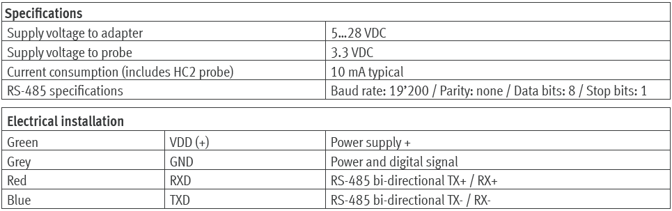
- US-RS485-WE-1800-BT (RS485 to USB converter: Third party device, not supplied by Rotronic). The E2-05XX-MODBUS and the US-RS485-WE-1800-BT need to be connected together based upon the connection diagram of both devices.
- RMS-CONFIG Software.
- A MODBUS master software (Third party software, not supplied by Rotronic).
- A Hex to Floating point converter (Third party software, not supplied by Rotronic).
| Step 1 | Review the RMS-HCD MODBUS address of the RMS-HCD probe with the RMS-CONFIG software. Plug the RMS-HCD into the AC3001 probe and add a local Device. |
|---|---|
| Step 2 | Check the MODBUS address under the Info of the Device Settings. The default address is 247: 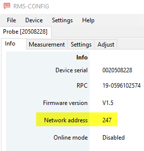 |
| Step 3 | We recommend setting the probe into simulator mode to simplify reading out the data. This is done under the RMS-CONFIG Settings. For this example, we have set a fixed value of 35.12%rh. |
| Step 4 | Plug the RMS-HCD into the E2-05XX-MODBUS/US-RS485-WE-1800-BT combination. Plug the setup into a USB port. |
| Step 5 | Open up the MODBUS master software tool and input the following details: - Modbus RTU. - Baudrate: 19200. - Parity: None. - Data bits 8. - Stop bits 1. - Slave ID 247. 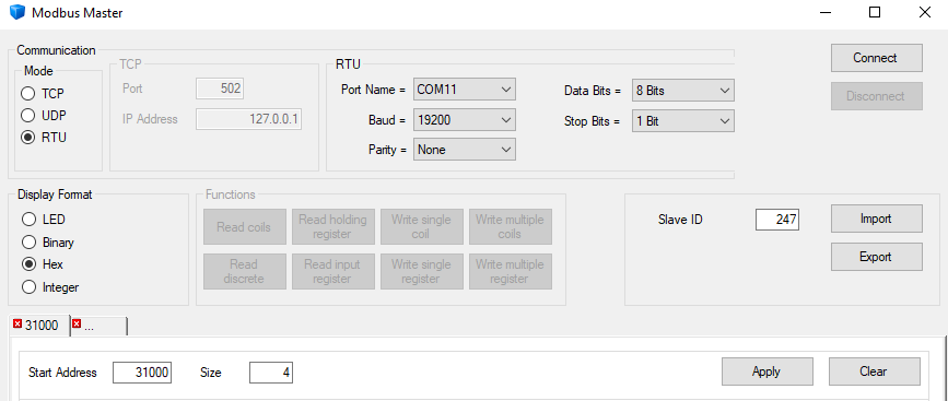 The port name will depend on the computer/port being used. |
| Step 6 | Press connect, the communication log will show if the connection was successful: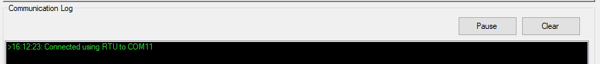 |
| Step 7 | The MODBUS address overview can be reviewed here: MODBUS. The addresses 31000 and 31001 are the humidity values (RS485 Address is the Register address -1): 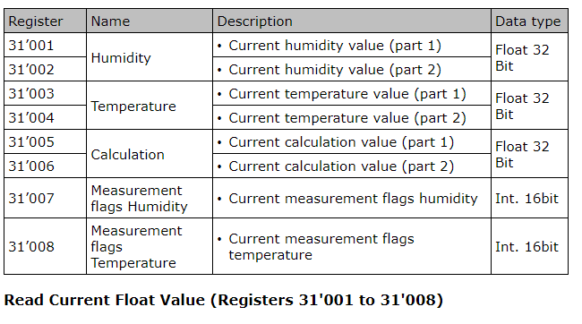 |
| Step 8 | Under the MODBUS Master software, add the start address 31000 and size 4 and press "Apply", then press "Read input register": 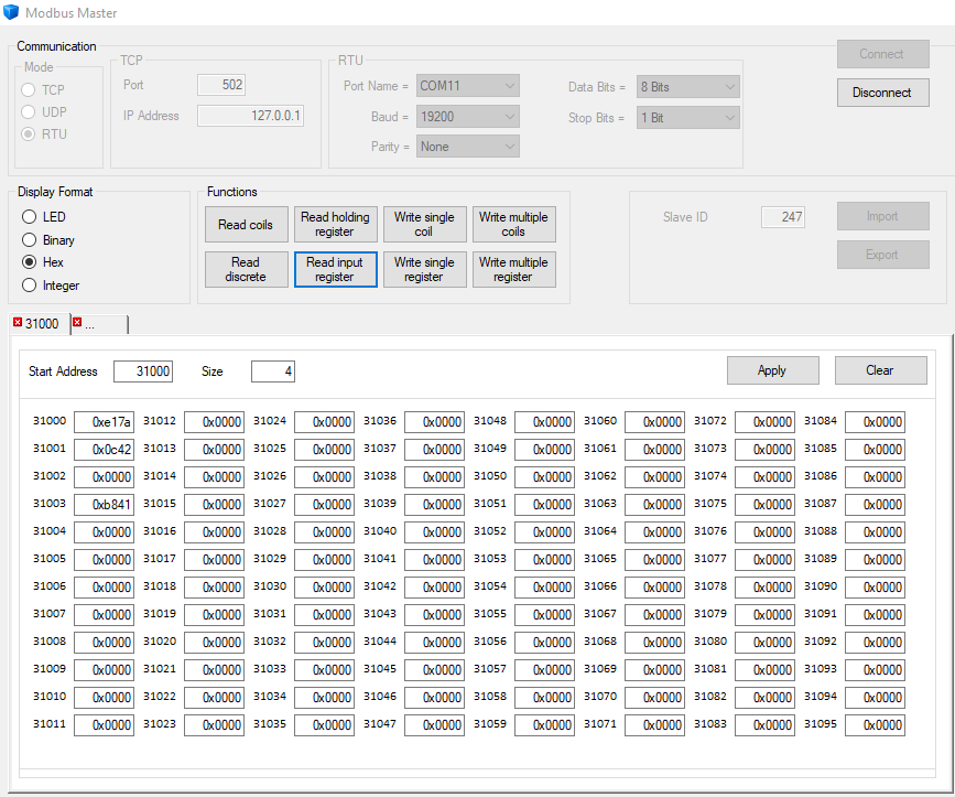 The data received: - 31000: 0xe17a - 31001: 0x0c42 |
| Step 9 | Swap format: the standard setting is 0x0001 with target bytes d c b a: 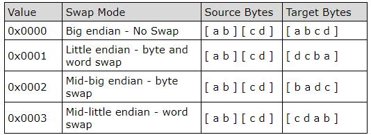 As the target bytes are d c b a, the hex value is 42 0c 7a e1. |
| Step 10 | In order to calculate the decimal value, the hex to floating point converter is required. We have used an online tool: 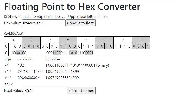 The float value gives us 35.12, which corresponds to the 35.12%rh simulator mode that has been applied. |
| Step 11 | It is possible to change the swap format if required: - Start address: 40001 - Size: 1 - Address: 4001 Type in 0000 for Target bytes a b c d - Press "Apply" - Press "Write single register" 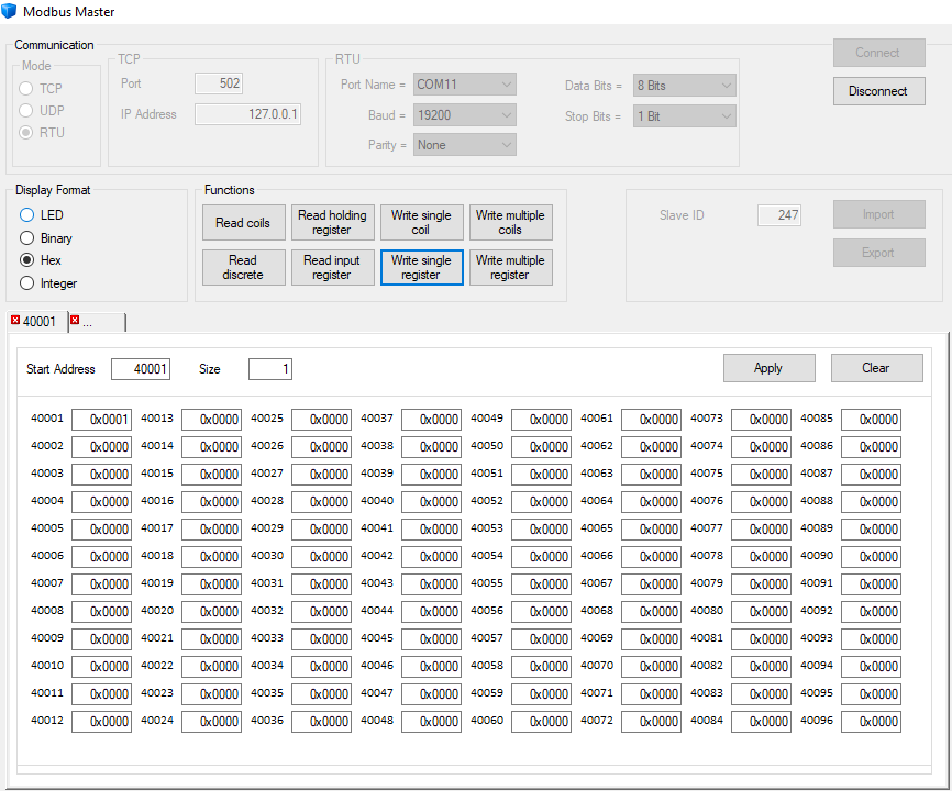 |
| Step 12 | Read humidity values again: 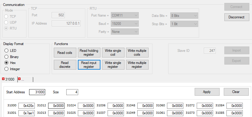 The data received: - 31000: 0x420c - 31001: 0x7ae1 |
| Step 13 | Swap format: the standard setting is 0x0000 with target bytes a b c d: As the target bytes are a b c d, the hex value is 42 0c 7a e1. |
| Step 14 | Check again with the calculator: 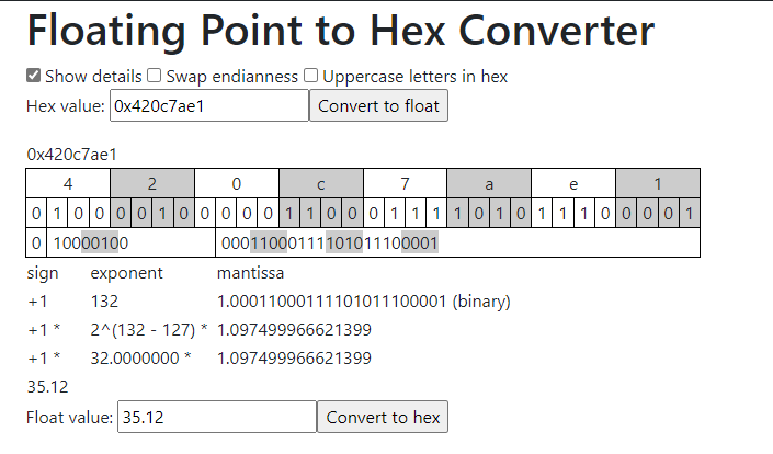 The float value gives us 35.12, which corresponds to the 35.12%rh simulator mode that has been applied. |