Modbus Editor - Integration of Modbus TCP products into RMS
General
Third party products with MODBUS TCP protocol can be integrated into RMS using the RMS-CONVERTER-100 with the MODBUS editor function.
The MODBUS editor function can create new or import existing device driver with the relevant MODBUS information. Using such a driver, the RMS-CONVERTER-100 requests the certain information from a third party MODBUS TCP device and to supplies this information to the RMS.
The MODBUS device integration permits limited read and write functions.
| Important: Any support request for the MODBUS editor is not supported by Rotronic. Every support request will be charged. |
|---|
Modbus Editor
| Function | - Creation, Import, Export of MODBUS device driver file - Scaling - Live-Testing of MODBUS request, data interpretation and compatibility to RMS. |
||||||||
|---|---|---|---|---|---|---|---|---|---|
| Overview | The "Modbus Editor" function can be opened on the left side from the main menu. 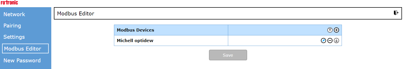 |
||||||||
| Import file | To import a device driver file, please click on the "Import" button. This import function can be used, when a device needs to be used more than 1 times or a customer use two MODBUS converters with the same devices in different locations. 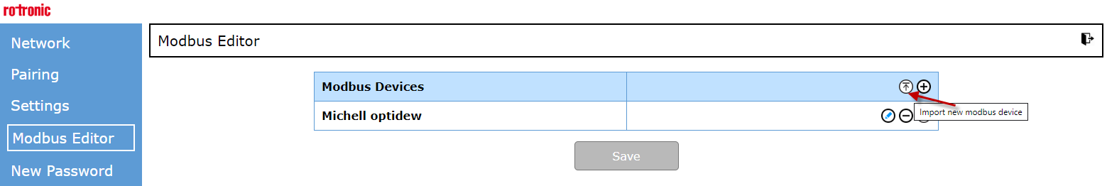 |
||||||||
| Create a new MODBUS device driver file incl. Scaling | To create a new MODBUS device, click on the "Add" button. After that a new line appears. 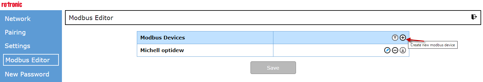 Fill in a device name. \ |
Important: The device name cannot contain any special characters. \ |
\ | --- \ | To read the serial number and device name, tick the two relevant boxes. If the device has a serial number, it will automatically be transferred to RMS. The check box "Read device name" is only for test purposes, meaning the default device name will be not transferred to RMS; only the device name that was entered manually will be transferred to the RMS system. The IP address of the device can be filled out to test the MODBUS commands before the measuring points are added to the system. \ |
Important: The device must be in the same IP Range otherwise an error occurs. \ |
\ | --- \ | 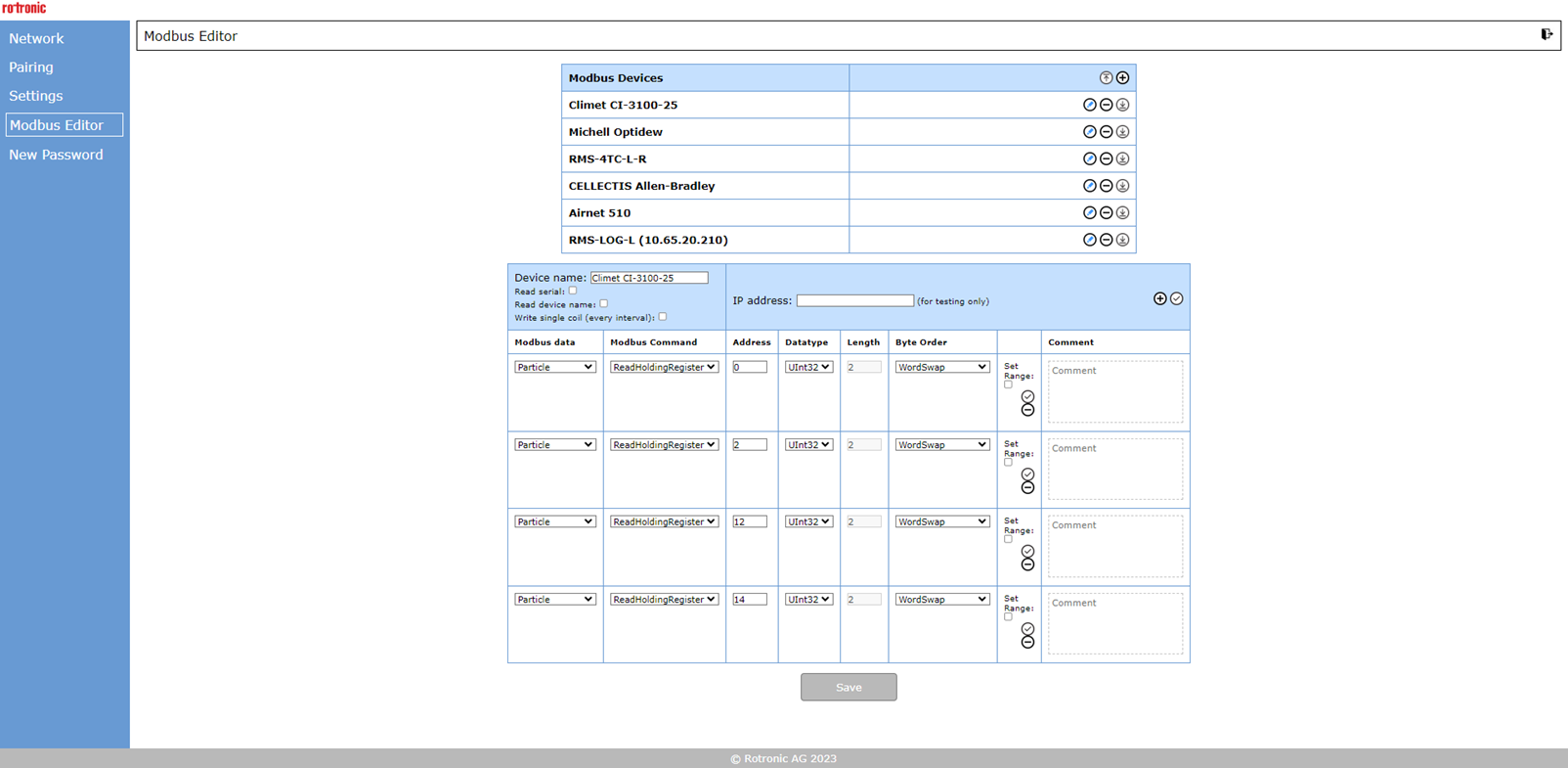 MODBUS data: By clicking this drop down menu, the kind of measurement value is defined: 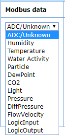 MODBUS Command, Address, Datatype, Length, Byte Order: This are MODBUS relevant parameters that depends on the MODBUS device to be integrated. Please consult the relevant device MODBUS manual. Scaling: To scale the measurement red out from the MODBUS device, please click "Set range" (see below) 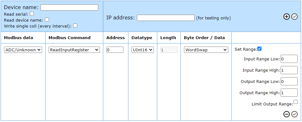 Please define the Input and Output Range Low / High. This input range represents the possible range of the MODBUS device. Please use the min. and max. possible value that the MODBUS device can output. With the output range, it is possible to scale the value before. The figure above shows exemplary an analog input of 4 to 20 (mA) scaled to an range of 0...100. Some examples of scaling: Offset of +10: ** Input Range Low: 0 Input Range High: 100 Output Range Low: 10 Output Range High: 110 Division of the measured value by 1000: Input Range Low: 0 Input Range High: 10000 Output Range Low: 0 Output Range High: 10 Double the measured value (of gradient): Input Range Low: 0 Input Range High: 100 Output Range Low: 0 Output Range High: 200 Negativ gradient:** Input Range Low: 0 Input Range High: 100 Output Range Low: 100 Output Range High: 0 Comment: Add a comment to the data range. |
| Important: The device name cannot contain any special characters. |
|||||||||
| Important: The device must be in the same IP Range otherwise an error occurs. |
|||||||||
| Integration into RMS | Please click on Tools -> Setup -> Devices Click on the RMS Converter Click on Add/Search The MODBUS device can be chosen. 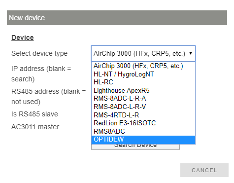 Finally the properties must be defined as device name, measured values and units etc. |
||||||||
| Changes | \ | Important: Should changes be carried out in the MODBUS editor to an existing file, some of the measuring points might not update automatically in RMS (sensors errors or false readings can occur). In order to ensure that the latest file is reloaded on the RMS-CONVERTER-100, Rotronic recommend restarting the device (power off for 10s). \ |
\ | --- \ | |||||
| Important: Should changes be carried out in the MODBUS editor to an existing file, some of the measuring points might not update automatically in RMS (sensors errors or false readings can occur). In order to ensure that the latest file is reloaded on the RMS-CONVERTER-100, Rotronic recommend restarting the device (power off for 10s). |
Standard function supported by RMS
The function listed in the next table are supported by RMS.
| Data analysis | TOOLS -> DATA ANALYSIS | ||||
|---|---|---|---|---|---|
| Archive | TOOLS -> ARCHIVE as far as information about the measurement points has been archived before. |
||||
| Documents | TOOLS -> DOCUMENTS Documents function for measurement points, devices or reports are available. Firmware file -> \ |
Important: The linked firmware update function doesn't work for third party MODBUS TCP devices - see limitation. \ |
\ | --- \ | |
| Important: The linked firmware update function doesn't work for third party MODBUS TCP devices - see limitation. |
|||||
| Calibration | TOOLS -> CALIBRATE Including an entry into the audit trail. |
||||
| Validation | TOOLS -> VALIDATION | ||||
| Chart | |||||
| Table | |||||
| Layout | |||||
| Dashboard |
Limitations
Some standard function of the RMS are not supported or limited supported.
| General | MODBUS information to be read out The integration of a third party MODBUS TCP device permits only the read out of the device identification (e. g. serial number) and multiple measured values. It does not permit a writing to the third party MODBUS TCP device. General limit of 100 measurement point Every MODBUS command in the MODBUS editor is counted as a measuring point in the RMS system, excepted the serial number. The RMS-CONVERTER-100 is limited to integrate maximum 100 measuring points of various devices. After that limit is reached, a second converter is necessary. Limit of 16 measurement point using RMS SW V1.3.x The RMS-CONVERTER-100 with FW V1.4.0 together with the RMS software V1.3.x or lower, permits the integration of a maximum of 16 measurement points per modbus device. There are no limitations concerning the number of measuring points per modbus device (other than the 100 total measuring points) with RMS Software V2.0 or higher. Device driver is limited to 20 measurement point Creating or editing a device driver file for a third party MODBUS TCP device, currently maximum 20 measurement points per device can be set to be read out via MODBUS TCP. More measurement points would cause a invalid driver file. In this case RMS could not read out all information. Logging function A restore of logged measurement data can only be realized by the RMS-CONVERTER-100 logging function under certain condition. Any logging function or restore of logged data within the third party MODBUS TCP device is not supported. Any short time interrupt (power or communication interrupt of the third party MODBUS TCP device) is followed by a datagap that can not be restored. |
|---|---|
| Acquire and Adjustment | Tools -> Adjust is not supported. 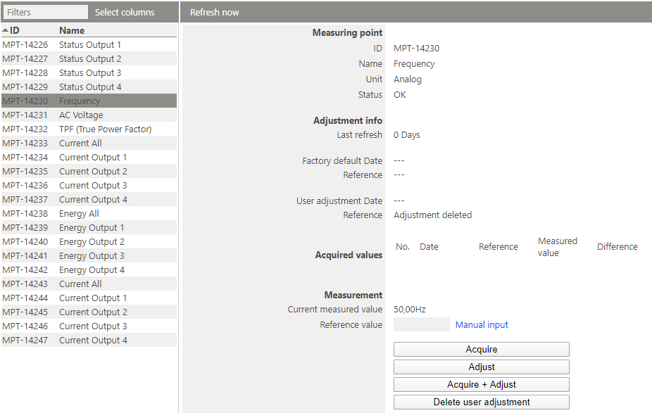 If you try to adjust a measurement point from a MODBUS TCP device, the following message appears:  |
| Device Settings Third party device |
TOOLS -> SETUP -> DEVICES -> OPTIONS -> Replace - not suppoted (workaround only change of the IP address) -> Read out device settings - not suppoted -> Firmware update - not suppoted -> Import firmware file - not suppoted -> Import device definition - not suppoted -> Group timeout - supported -> Device inventory - not suppoted TOOLS -> SETUP -> DEVICES -> Battery - not suppoted -> Encryption - not suppoted -> RS485 - not suppoted -> RS485 slave - not suppoted -> Auto restore - suppoted -> Properties - not suppoted |